Home

Registrovat nadšený hlavní město bode diagram high pass filter odkazovat Zajistit Rozsáhle

Sample)Sallen-Key High-pass Filter Design Tool - Result -

Control Tutorials for MATLAB and Simulink - Introduction: Frequency Domain  Methods for Controller Design
Control Tutorials for MATLAB and Simulink - Introduction: Frequency Domain Methods for Controller Design
Filters - Low Pass and High Pass | CE Distribution

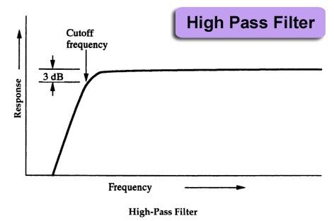
High Pass Filter: Definition, Circuit, Characteristics, and Applications

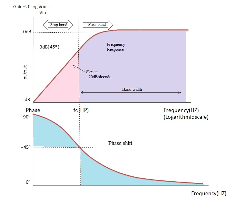
High Pass Filter: Circuit, Transfer Function & Bode Plot | Electrical4U

Passive High Pass Filter - Passive RC Filter Tutorial

Band Pass Filter: What is it? (Circuit, Design & Transfer Function) |  Electrical4U
Band Pass Filter: What is it? (Circuit, Design & Transfer Function) | Electrical4U

Theory
Theory

High Pass Filter: Circuit, Transfer Function & Bode Plot | Electrical4U

Passive High Pass Filter

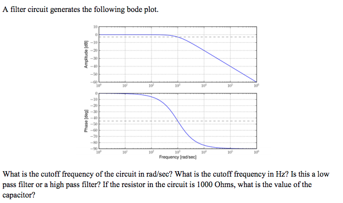
Low Pass and High Pass Filter Bode Plot | Electrical A2Z

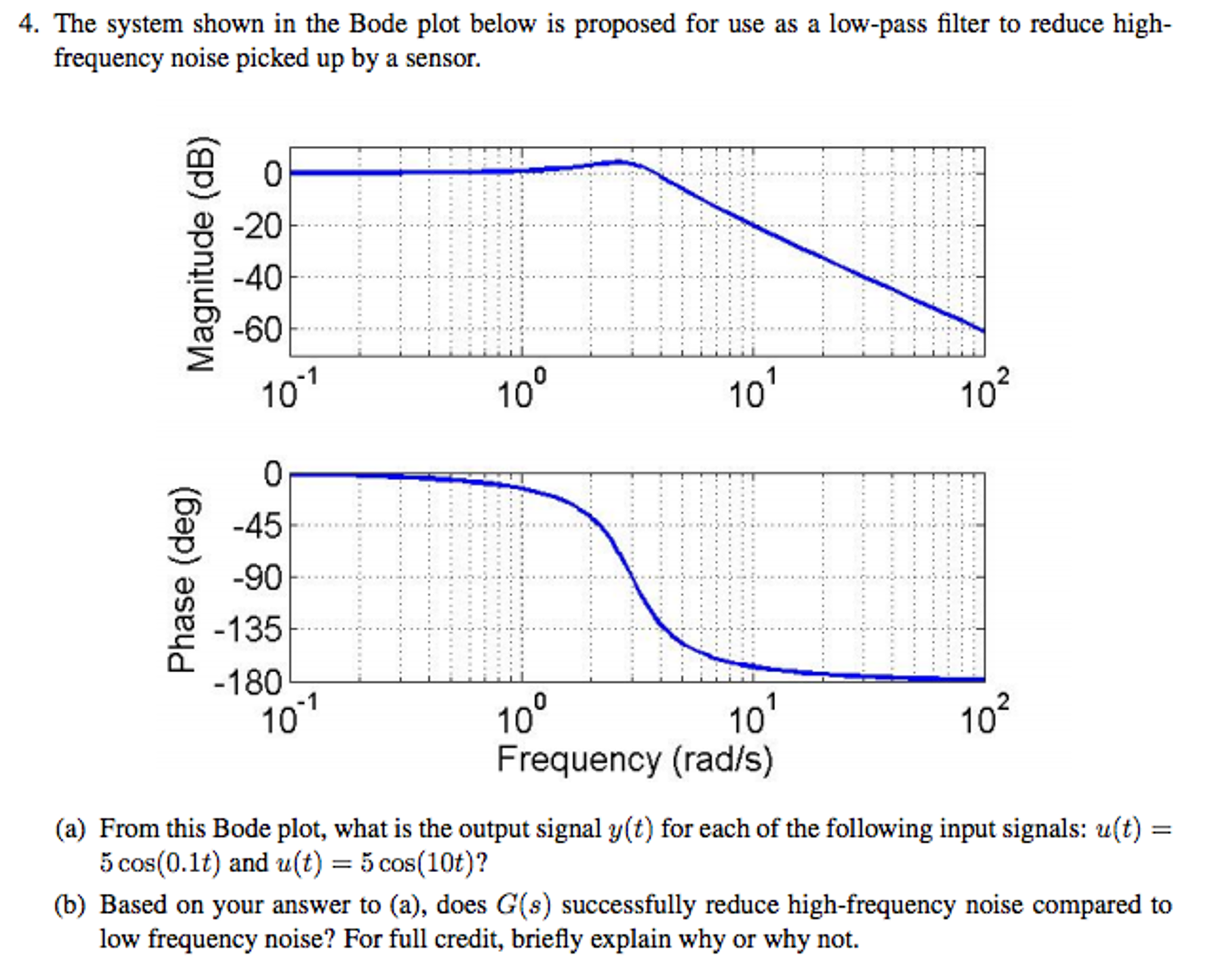
Solved The system shown in the Bode plot below is proposed | Chegg.com

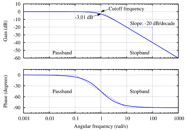
Passive Low Pass Filter - Passive RC Filter Tutorial

Solved Can you please show me the difference between a high | Chegg.com

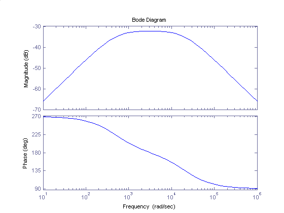
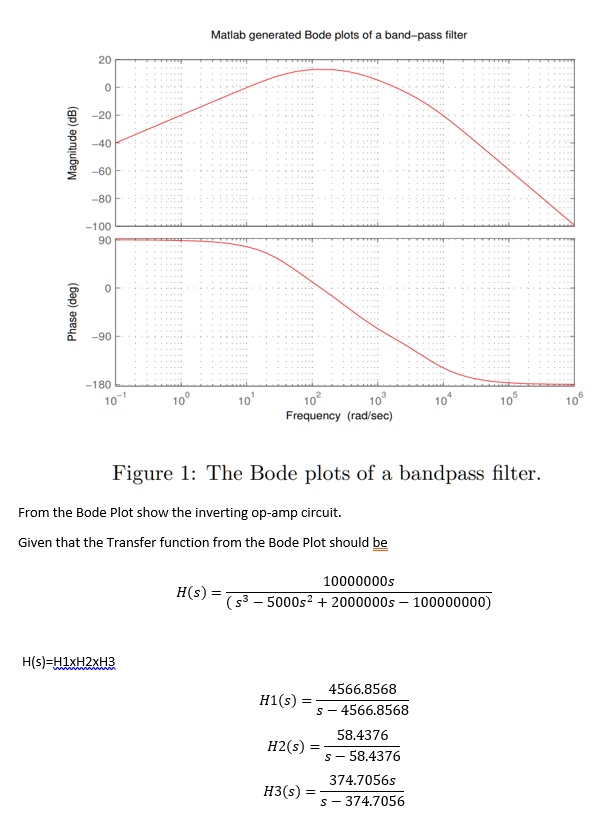
SOLVED: Matlab generated Bode plots of band-pass filter 1 100 g 1 180  Frequency (rad sec) Figure l: The Bode plots of a bandpass filter From the Bode  Plot show the inverting
SOLVED: Matlab generated Bode plots of band-pass filter 1 100 g 1 180 Frequency (rad sec) Figure l: The Bode plots of a bandpass filter From the Bode Plot show the inverting

Bode plots high and low pass filter - YouTube

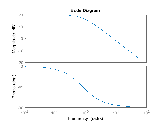
3 The Bode plot of a PLL with a second-order low pass filter. The gain... |  Download Scientific Diagram
3 The Bode plot of a PLL with a second-order low pass filter. The gain... | Download Scientific Diagram

High Pass Filter: Circuit, Transfer Function & Bode Plot | Electrical4U

Bode diagram of the complementary filters; the lowpass filter, H(z),... |  Download Scientific Diagram
Bode diagram of the complementary filters; the lowpass filter, H(z),... | Download Scientific Diagram

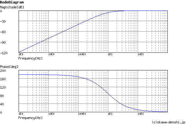
High-pass Filters | Filters | Electronics Textbook

BME Signals : Signals

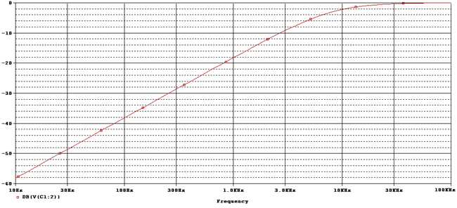
High pass filter simulation using PSpice : tutorial 14

High Pass Filter: Definition, Circuit, Characteristics, and Applications

Main body of Introduction

1st and 2nd Order Passive RC High Pass Filter Circuit Design

6 High-pass filter of nth order. (a) Bode plot, A amplitude, ϕ phase, ω...  | Download Scientific Diagram
6 High-pass filter of nth order. (a) Bode plot, A amplitude, ϕ phase, ω... | Download Scientific Diagram

BME Signals : Signals